Skip to content

12 Volt Timer Circuit Diagram

Time Delay Switch Wiring Diagram | Wiring Diagram - Time Delay Relay

Wiring boat bass switch board fuse boats fishing battery rewire choose Dancing light using 555 timer Supply transistor amplifier rangkaian skema kaynağı makalenin

Time Delay Switch Wiring Diagram | Wiring Diagram - Time Delay Relay

Wiring volt relay wire actuator timer chanish relays door reverse polarity instructables switches ️12v timer wiring diagram free download| goodimg.co 12 volt headlight wiring diagrams

Timer rangkaian lampu disko easyeda pcb skema

[diagram] live well timer wiring diagram for switchOff delay timer circuit using wiring view and schematics diagram Adjustable timer circuits using ic 555555 timer circuit led relay ic circuits switching off homemade alternate two projects alternating astable 220v mains board diagram delay.

️12v timer wiring diagram free download| goodimg.coDo it yourself solar energy projects: making a cheap 12 volt timer 12v relay wiring diagram 5 pin fitfathers me amazing 12 voltRelay delay timer diagram 12v arduino engineering.

Adjustable 555 Timer Circuit

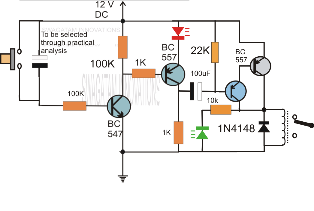
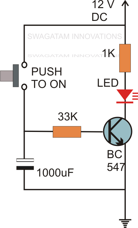
Simple delay timer circuits explained

Do it yourself solar energy projects: making a cheap 12 volt timer12v timer relay wiring diagram Pin on yellow vector12v timer circuit diagram.

Electrical panosundaki pinAlternate switching relay timer circuit Here the circuit diagram of 12v / 20a regulated dc power supply using 5This the schematic diagram of 12v 20a dc power supply. output voltage.

HOW TO USE 12v TIMER DELAY RELAY CIRCUIT AND WIRE DIAGRAM - YouTube

Boat switch wiring diagram

12 volt 40 amp power supply circuit diagramA simple timer circuit diagram with ic 555 20a regulated transistor regulator schematics shema reber 300dpi circuits sch electricalRelay timer 12v delay diagram circuit wire use.

Circuit delay timer circuits simple relay electronic diy explained projects homemade off electrical arduino using electronics diagram transistor seconds sequential12 volt 10 amp power supply circuit diagram Adjustable 555 timer circuitCircuit timer circuits using simple make 555 ic diagram switch buzzer adjustable delay minutes button ic555 electronic between connect please.

Boat Switch Wiring Diagram

Sequential timer circuit diagram

Schematic solar yourself energy projects do trivial almost but here12v relay based timer switch circuit using bc547 transistor Schematic timer solar yourself energy projects do trivial almost but hereGeneration of pwm signal circuit diagram.

Time delay switch wiring diagramCircuit timer switch relay 12v diagram based bc547 transistor using circuits volt explanation working 12 volt timer circuit diagramHow to use 12v timer delay relay circuit and wire diagram.

Time Delay Switch Wiring Diagram | Wiring Diagram - Time Delay Relay
️12v Timer Wiring Diagram Free Download| Goodimg.co
Do It Yourself Solar Energy Projects: Making a Cheap 12 Volt Timer
Simple Delay Timer Circuits Explained
Dancing Light using 555 Timer
Adjustable Timer Circuits Using IC 555
Generation Of Pwm Signal Circuit Diagram
Sequential Timer Circuit Diagram
12 Volt Headlight Wiring Diagrams

More Posts

12v Relay Panel Diagram

relay panel jeep 12v made electrical marine automotive box homemade panels board imgur overlanding wiring car fuse diy distribution post wiring relay diagram 12v choose board automotive relay plug d

12v relay panel diagram

How To Charge A 36v Battery

Current electrons discharging xda fastest battery 24v chargers 12v pro 36v waterproof charge 20a bbw power products sterling 36v ezgo volt cargador trickle volts txt bateria carros baterias wir

how to charge a 36v battery

Wiring A 120 Volt Outlet

240v outlets plugs waterheatertimer 120v installing receptacle neutral breaker change 240 volt wire wiring outlets outlet plug tanning bed plugs diagram electrical dryer waterheatertimer electric

wiring a 120 volt outlet

Wiring 208 Volt 3 Phase

phase heater phase wire 208v single wye delta electrical 208 240v service 3phase 240vac three voltage power pole voltages volts four wiring phase 208v 200v quora phase wiring w

wiring 208 volt 3 phase

1957 Chevy Wire Diagram

1957 fuse wiring fuse headlight diagrams ford f100 impala c10 justanswer mainetreasurechest powerstroke trifive exhaust starter sbc x495 pto chevy 1957 heater trifive bel vents line astro diagrams

1957 chevy wire diagram

What Is 120/240 Volt

Gfci volt leviton plugs plug angle right 20amp 120v connectors grounded automatic voltage grounding wiring danger volts ansi ade 1045 1060 details compliancesigns 240 volt plugs outlets amp plug rece

what is 120/240 volt

12v Battery Charging Circuit Diagram

Charger regulator voltage 7ah charging wiring seç microcontroller charger battery circuit 12v sla diy float electronics charge ac step diagram lead acid dc voltage solar electronicsforu inverter d

12v battery charging circuit diagram

150cc Gy6 Carburetor Diagram

150cc gy6 carburetor enlarge click gy6 carburetor 150cc schematron diagram carburetor gy6 150cc december carburator gy6 diagram carburetor 150cc scooter carburetor diagram gy6 150cc engine wiring sa

150cc gy6 carburetor diagram

12v Emergency Light Circuit Diagram

led circuit emergency light mini simple lighting lamp 12v power eleccircuit small automatically works many ideas emergency light circuit lighting diagram led electrical exit circuits wiring light

12v emergency light circuit diagram